Flink Task调度部署机制

开发 前端
Flink开源社区较活跃,Task侧的部署链路也一直在演进中,持续跟进并深入了解内部实现逻辑能更好的支持我们解决Flink个性化调度策略上的一些问题。

1背景

在日常Flink使用过程中,我们经常遇到Flink任务中某些Slot或者TM负载过重的问题,对日常的资源调配、运维以及降本都带来了很大的影响,所以我们对Flink的task部署机制进行了梳理和调研,准备在后续的工作中进行优化。由于jobGraph的生成以及任务提交流程因任务部署方式而不同,对我们后续的分析也没有影响,这里忽略前置流程,直接从Dispatcher出发,重点关注submit后executionGraph构建以及后续的任务部署过程。

2Flink Scheduling Components 构成

2.1   SchedulerNG

在Dispatcher收到submit请求后,先是启动了JobManagerRunner,再启动JobMaster,在初始化jobMaster的过程中,我们注意到这里开始了整个作业的Scheduling第一步,创建SchedulerNG。

this.schedulerNG =
createScheduler(
slotPoolServiceSchedulerFactory,
executionDeploymentTracker,
jobManagerJobMetricGroup,
jobStatusListener);

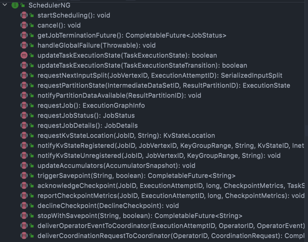
我们看下SchedulerNG的职责,可以看到调度的发起,作业状态的跟踪以及我们熟悉的cp,sp的trigger都是在这里:
图片

我们这次主要跟踪构建executionGraph,然后根据Scheduling策略发起的整个部署过程。

2.2   ExecutionGraph

现阶段(1.13)SchedulerNG默认实现是DefaultScheduler,初始化过程中就会开始构建我们的ExecutionGraph,ExecutionGraph中有几个重要元素

  1. ExecutionJobVertex: 代表jobGraph中的一个JobVertex,是所有并行Task的集合
  2. ExecutionVertex: 代表ExecutionJobVertex中并行task中的一个,一个ExecutionJobVertex可能同时有很多并行运行的ExecutionVertex
  3. Execution: 代表ExecutionVertex的一次部署/执行,一个ExecutionVertex可能会有很多次Execution

这里executionGraph通过jobGraph的拓扑图构建了自己的核心结构,看下从JobVertex到ExecutionJobVertex 的转换流程:

// topologically sort the job vertices and attach the graph to the existing one
List<JobVertex> sortedTopology = jobGraph.getVerticesSortedTopologicallyFromSources();
executionGraph.attachJobGraph(sortedTopology){
1. executionGraph第一步拿到了jobGraph中的有序JobVertex列表
2. 接着一对一创建ExecutionJobVertex
3. 根据producer并行度生成producedDataSets(IntermediateDataSet)
4. 再根据自身并行度生成所属的ExecutionVertex[]
5. 构建stateBackend信息和checkpointStorage信息等
6. 最后完成executionGraph的拓扑构建executionTopology
}

2.3   执行层拓扑结构

我们知道Flink引擎在不停的致力于批流一体建设,调度层的统一也是其中核心的一层。为了提高failover后recovery速度,减少对Flink任务的影响,现在Flink对于批、流的任务task调度都是以pipeline region为基础。

Pipeline region的构建内嵌在executionGraph的初始化过程中,我们知道Flink中各个节点之间的链接都会有IntermediateDataSet这一种逻辑结构,用来表示JobVertex的输出,即该JobVertex中包含的算子会产生的数据集。这个数据集的ResultPartitionType有几种类型:

BLOCKING:都上游处理完数据后,再交给下游处理。这个数据分区可以被消费多次,也可以并发消费。这个分区并不会被自动销毁,而是交给调度器判断。
BLOCKING_PERSISTENT:类似于Blocking,但是其生命周期由用户端指定。调用JobMaster或者ResourceManager的API来销毁,而不是由调度器控制。
PIPELINED:流交换模式。可以用于有界和无界流。这种分区类型的数据只能被每个消费者消费一次。且这种分区可以保留任意数据。
PIPELINED_BOUNDED:该策略在PIPELINED的基础上保留有限制的buffer,避免对barrier造成阻塞。
PIPELINED_APPROXIMATE:和PIPELINED_BOUNDED类似,可以支持下游task重启后继续消费,用来支持task failover后的Approximate Local-Recovery策略。

接下来我们看看executionGraph的核心拓扑结构ExecutionTopology是如何构建的:

第一步 先根据executionTopology构建rawPipelinedRegions,多个vertex能否组合成一个pipeline region的关键在于这个vertex的consumedResult.getResultType().isReconnectable(),如果支持重连,那么两个vertex之间就会进行拆分,划到不同的region。这里的isReconnectable就和我们的ResultPartitionType类型有关,流处理中的PIPELINED和PIPELINED_BOUNDED都是默认的false,在这种情况下所有的vertex其实都会放入同一个region。故我们日常的flink作业其实都只会生成一个pipeline region。
第二步 根据不同的pipeline region构建自己的resultPartition信息,这个是为了构建后续的PartitionReleaseStrategy,决定一个resultPartition何时finish以及被release
第三步 对vertex的coLocation情况进行校验,保证co-located tasks必须在同一个pipeline Region里。这里是因为后续的scheduling strategy里会保证不同pipeline region的调度部署是阶段隔离的,可能无法满足colocation-constraint

2.4   Scheduling 策略

SchedulerNG Scheduling策略默认为PipelinedRegionSchedulingStrategy,在executionGraph完成之后,就可以根据生成的刚刚executionTopology来初步构建初步的Scheduling策略了。这里看下startScheduling代码,可以看到Scheduling过程就是我们常说的基于pipeline region的Scheduling。

@Override
public void startScheduling() {
final Set<SchedulingPipelinedRegion> sourceRegions =
IterableUtils.toStream(schedulingTopology.getAllPipelinedRegions())
.filter(this::isSourceRegion)
.collect(Collectors.toSet());
maybeScheduleRegions(sourceRegions);
}

2.5   Execution Slot 分配器

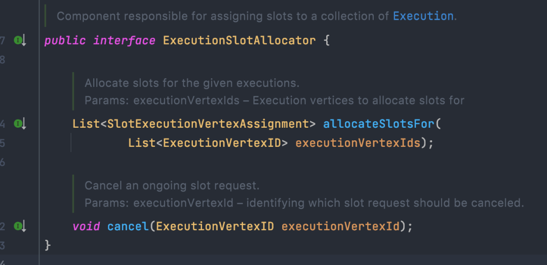
默认实现是SlotSharingExecutionSlotAllocator,在schedulerNG完成executionGraph构建完成后,需要进一步构建Execution Slot 分配器。用于将physical shared slots分配到我们的logical slots 上,并将logical slot 分配给我们executionGraph中的execution(task)。通过代码我们可以看到ExecutionSlotAllocator的职责非常简单,只有简单的allocate和cancel。
图片

但在实现上这里有几个重要元素需要了解:

LocalInputPreferredSlotSharingStrategy :在Flink内部,所有的slot分配都是基于sharingslot来操作的,在满足co-location的基础上,Flink期望将producer和consumeNode task尽可能的分布在一起,以减少数据传输成本。

SlotProfile:slot的资源信息,对task -> logical slot -> physical slot的mapping有非常重要的作用,包含了task的资源信息,slot的物理资源信息,倾向的location(TaskManagerLocation),倾向的allocation以及整个executionGraph之前分配过的allocation(用于黑名单,重启后尽量避免分配在之前的slot里)。

ResourceProfileRetriever: 用于获取executionVertex的实际资源信息。默认是unknown,如果有明细配置会用于后续的executionSlotSharingGroup资源构建。

ExecutionSlotSharingGroup:Flink task资源申请的最终逻辑载体,用于将sharing到一起的task(execution group)组合成一个group用于生成资源,后续部署也会绑定对应的task。

3Scheduling 主要过程

在JobMaster完成自身构建之后,就委托SchedulerNG来开始了整个job的Scheduling:

@Override
protected void startSchedulingInternal() {
log.info(
"Starting scheduling with scheduling strategy [{}]",
schedulingStrategy.getClass().getName());
transitionToRunning();
schedulingStrategy.startScheduling();
}

可以看到这里是由schedulingStrategy来负责整个调度过程的,也就是我们的PipelinedRegionSchedulingStrategy

one by one将pipeline region进行部署

private void maybeScheduleRegions(final Set<SchedulingPipelinedRegion> regions) {
final List<SchedulingPipelinedRegion> regionsSorted =
SchedulingStrategyUtils.sortPipelinedRegionsInTopologicalOrder(
schedulingTopology, regions);


final Map<ConsumedPartitionGroup, Boolean> consumableStatusCache = new HashMap<>();
for (SchedulingPipelinedRegion region : regionsSorted) {
maybeScheduleRegion(region, consumableStatusCache);
}
}

遍历region中的ExecutionVertex依次进行部署

final List<ExecutionVertexDeploymentOption> vertexDeploymentOptions =
SchedulingStrategyUtils.createExecutionVertexDeploymentOptions(
regionVerticesSorted.get(region), id -> deploymentOption);
schedulerOperations.allocateSlotsAndDeploy(vertexDeploymentOptions);

将vertexDeployment交给SlotSharingExecutionSlotAllocator处理

private List<SlotExecutionVertexAssignment> allocateSlots(
final List<ExecutionVertexDeploymentOption> executionVertexDeploymentOptions) {
return executionSlotAllocator.allocateSlotsFor(
executionVertexDeploymentOptions.stream()
.map(ExecutionVertexDeploymentOption::getExecutionVertexId)
.collect(Collectors.toList()));
}
接下来整个allocate的主要过程如下(忽略physical fail等情况)

通过SlotSharingStrategy拿到每个execution对应的ExecutionSlotSharingGroup

  1. 先从 corresponding co-location constraint 去mapping中寻找是否有存在的slot sharing group
  2. 接着从producer 的角度来逐一检查是否可以合并到同一个slot sharing group.
  3. 最后尝试所有剩下的slot sharing group看是否符合execution 的要求(如同属于一个job vertex的task不能分配到同一个 slot sharing group).
  4. 如果以上都没有满足条件的就创建一个新的slot sharing group
  1. 检查ExecutionSlotSharingGroup是否已经有了对应的sharedSlot
  2. 遍历尚未得到分配的ExecutionSlotSharingGroup
  3. 计算对应的SlotProfile
  4. 向PhysicalSlotProvider申请新的physical slot
  1. rm侧会先检查是否已经有满足条件的excess slot

  2. 如果没有尝试会申请新的woker以提供资源

  3. 由sharedSlotProfileRetriever来创建对应的slotProfile并构建PhysicalSlotRequest

  4. PhysicalSlotProvider向slotPool申请新的slot

  5. slotPool会向rm侧申请新的slot

  1. 利用physical slot  future提前创建sharedSlotFutrue

  2. 将sharedSlotFutrue 分配给所有相关的executions

  3. 最后生成所有的SlotExecutionVertexAssignments

在完成所有的SlotExecutionVertexAssignment之后,生成对应的DeploymentHandle并等待所有的assignedSlot创建完毕,正式开始部署对应的任务。​

4问题思考

我们对整个Flink task的部署过程完成梳理后,重新对我们一开始的问题进行思考:

4.1   为什么会出现slot负载过重的情况?如何避免?

问题的产生在于大量的task集中分配到了统一个sharedSlot,这个我们可以发现其实是在ExecutionSlotSharingGroup的构建过程中产生的。我们看下源码,可以很直接的看到整个group的分配是一个roundRobin过程,而executionVertices来自于有序拓扑结构,中间传递过程也保证了有序性,所以最终会导致大量的task分配的index靠前的group中,最后落到了同一个slot。

为了避免这种情况,我们的做法其实有比较多,一种是在保证各种constraint的同时添加随机性,以打散各个不均匀的task;还有一种就是构建基于load-balance的分配过程,以尽可能的将task分布均匀。

附Flink部分源码:

private void findAvailableOrCreateNewExecutionSlotSharingGroupFor(
final List<SchedulingExecutionVertex> executionVertices) {


for (SchedulingExecutionVertex executionVertex : executionVertices) {
final SlotSharingGroup slotSharingGroup =
getSlotSharingGroup(executionVertex.getId());
final List<ExecutionSlotSharingGroup> groups =
executionSlotSharingGroups.computeIfAbsent(
slotSharingGroup.getSlotSharingGroupId(), k -> new ArrayList<>());


ExecutionSlotSharingGroup group = null;
for (ExecutionSlotSharingGroup executionSlotSharingGroup : groups) {
if (isGroupAvailableForVertex(
executionSlotSharingGroup, executionVertex.getId())) {
group = executionSlotSharingGroup;
break;
}
}


if (group == null) {
group = new ExecutionSlotSharingGroup();
group.setResourceProfile(slotSharingGroup.getResourceProfile());
groups.add(group);
}


addVertexToExecutionSlotSharingGroup(executionVertex, group);
}
}
4.2   如何避免tm级别的负载过重?

这个问题主要是在于说有一些过重的task对应的slot都分配在了同一个tm上,导致整个tm压力过大,资源难以协调。在整个过程中其实我们有看到tm信息的交互,在co-location constraint上。我们看下该hint职责:

The co-location group is used to make sure that the i-th subtasks for iteration head and iteration tail are scheduled on the same TaskManager.

也就是说其实是为了解决算子间相同index的task数据传递之类的问题,但对于task的均衡负载无法介入。对此我们尝试去做的事情:

在当前不使用细粒度资源配置的情况下,考虑task-slot之间均衡分布的同事,task-tm也能做到一定的负载均衡。这种情况可以通过tm单slot来解决,也可以在保证task-slotSharingGroup足够随机性的同时,保证slotSharingGroup-tm的足够随机性。

在后续使用使用细粒度资源配置的情况下,不使用slotsharing,且将相同jobVertex对应的task尽量分布在同一个task当中。这个我们后续准备在slotProfile中加入jobVertex相关的tag,SlotAllocator做slot matching的时候加入jobVertex constraint来保证task的位置分配。

5写在最后

Flink开源社区较活跃,Task侧的部署链路也一直在演进中,持续跟进并深入了解内部实现逻辑能更好的支持我们解决Flink个性化调度策略上的一些问题。后续我们也准备进一步完善Flink在operator级别的细粒度资源配置能力,降低资源使用率的同时进一步提高Flink作业稳定性。

责任编辑:武晓燕 来源: 得物技术
相关推荐

2024-02-27 08:05:32

Flink分区机制数据传输

2014-01-06 17:09:10

ApacheMesos

2022-01-14 07:56:38

Checkpoint机制Flink

2021-11-02 06:58:55

FlinkWindow机制

2022-12-20 10:22:16

计算函数

2024-06-04 15:56:48

Task​.NET异步编程

2015-03-24 16:29:55

默认线程池java

2020-10-10 14:21:49

CDH6.3.2flink部署

2013-08-05 17:09:57

2023-06-20 07:32:04

2021-07-30 19:44:51

AndroidJava线程

2020-03-03 08:29:07

时延敏感网络TSN网络

2022-06-20 06:38:50

Flink批作业算子

2021-11-29 08:48:00

K8S KubernetesAirflow

2009-03-02 14:19:33

CiscoWi-Fi通话调度

2021-02-01 11:30:13

React前端调度

2022-05-19 08:47:30

Flinkwatermark窗口计算

2019-06-04 13:44:53

架构运维技术

2015-01-14 17:20:35

2024-01-29 08:07:42

FlinkYARN架构
点赞
收藏

51CTO技术栈公众号