之前详细介绍了calico的ipip、vxlan、bgp模式, 但是所有的k8s节点都是同网段的, 本篇使用ensp和workstation在自己家里就可以模拟测试跨网段k8s集群calico方案的纯bgp模式。
架构搭建
本测试搭建的是"每机柜独立自治系统"架构, 参考:The *AS Per Rack* model[1]
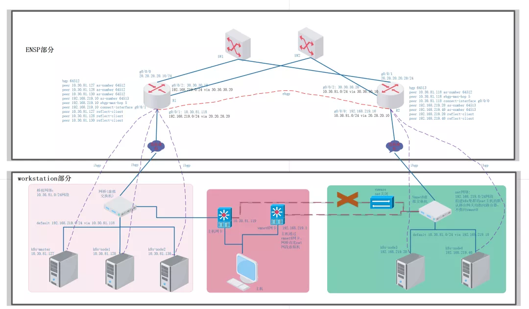
跨网段k8s集群架构
整个架构分为ensp部分和workstation部分, ensp部分主要是搭建出R1和R2的ebgp关系以及分别在R1和R2上添加各自网段内的k8s节点的bgp peer,workstation部分为构建跨网端的k8s集群。因为192.168.219.0/24网段的主机加入集群需要依赖ensp中的路由, 操作的顺序是先搭建出ensp的网络部分再将新节点加到k8s中继而配置bgp。现有k8s集群有三台服务器均通过桥接联网, 一台master节点两台普通节点, 分别如下
- k8s-master:10.30.81.127
- k8s-node1:10.30.81.128
- k8s-node2:10.30.81.130
ensp配置
按照上图搭建出ensp部分的网络设备连接拓扑, 然后分别配置R1、R2和两朵云, R1和R2上配置如下
- :'
- R1上配置
- '
- # 接口ip配置
- int g0/0/0
- ip a 20.20.20.10 24
- int g0/0/1
- ip a 10.30.81.118 24
- int g0/0/2
- ip a 30.30.30.10 24
- # 设置静态路由, 跳到下一个网段
- ip route-static 192.168.219.0 24 20.20.20.20
- ip route-static 192.168.219.0 24 30.30.30.20
- # bgp配置, 把同AS内的ibgp peer也配置了
- bgp 64512
- peer 10.30.81.127 as-number 64512
- peer 10.30.81.128 as-number 64512
- peer 10.30.81.130 as-number 64512
- peer 192.168.219.10 as-number 64513
- peer 192.168.219.10 ebgp-max-hop 5
- peer 192.168.219.10 connect-interface g0/0/1
- peer 10.30.81.127 reflect-client
- peer 10.30.81.128 reflect-client
- peer 10.30.81.130 reflect-client
- display bgp peer
- display bgp ip-routing
- display ip interface br
- display ip routing-table
- :'
- R2上配置
- '
- # 接口ip配置
- int g0/0/0
- ip a 192.168.219.10 24
- int g0/0/1
- ip a 20.20.20.20 24
- int g0/0/2
- ip a 30.30.30.20 24
- # 设置静态路由, 跳到下一个网段
- ip route-static 10.30.81.0 24 20.20.20.10
- ip route-static 10.30.81.0 24 30.30.30.10
- # bgp配置, 把同AS内的ibgp peer也配置了
- bgp 64513
- peer 10.30.81.118 as-number 64512
- peer 10.30.81.118 ebgp-max-hop 5
- peer 10.30.81.118 connect-interface g0/0/0
- peer 192.168.219.20 as-number 64513
- peer 192.168.219.40 as-number 64513
- peer 192.168.219.20 reflect-client
- peer 192.168.219.40 reflect-client
- display bgp peer
- display bgp ip-routing
- display ip interface br
- display ip routing-table
按如上配置好后R1和R2, 并且配置好两朵云后, 在R2上ping 10.30.81.118是可以成功的了, 并且我们也可以观察到R1和R2已经建立起了EBGP关系。但是从R2上ping k8s集群的任何一台主机都不通, 而是会报host unreachable, 因为k8s节点主机上并没有回程路由, 它们并不知道将icmp的replay包发往往R1, 因此需要在三台主机上添加路由
- # 此时添加如下路由也不会有效, 因为从R2上发出来的ping包源ip不是192.1168.219.0/24网段的
- route add -n 192.168.219.0/24 gw 10.30.81.118 dev ens33
- echo route add -n 192.168.219.0/24 gw 10.30.81.118 dev ens33 >> /etc/rc.local
- ip route add 192.168.219.0/24 via 10.30.81.118 dev ens33
- # 添加如下路由才会在R2上ping通现有k8s集群节点。 可以在ping通后删除掉, 因为R2只是中间节点而已
- route add -n 20.20.20.0/24 gw 10.30.81.118 dev ens33
- route add -n 30.30.30.0/24 gw 10.30.81.118 dev ens33
在k8s所有节点添加了如上的路由就可以在R2上ping通所有的k8s节点了
新机器加入k8s集群
创建虚机并配置它的网络为nat模式,配置它们的网卡和路由, 注意不要让它们有10.30.81.0/24网段的路由指向vmnet8。网卡配置如下
- # 网卡配置如下
- [root@k8s-node4 ~]# cat ifcfg-ens33
- TYPE=Ethernet
- DNS1=8.8.8.8
- IPADDR=192.168.219.40
- NETMASK=255.255.255.0
- GATEWAY=192.168.219.10
- BOOTPROTO=static
- DEFROUTE=yes
- IPV4_FAILURE_FATAL=no
- NAME=ens33
- UUID=6ef9b5bf-31c1-43b9-89d6-b8e89ab3c9c3
- DEVICE=ens33
- ONBOOT=yes
- # 下面的路由可以不加
- route add -net 10.30.81.0/24 gw 192.168.219.10 dev ens33
之后就是节点加入k8s的准备
系统配置, 如下
- echo "Stop Firewalld"
- systemctl stop firewalld
- systemctl disable firewalld
- sed -ie 's/SELINUX=enforcing/SELINUX=disabled/g' /etc/selinux/config
- setenforce 0
- echo "net.ipv4.ip_forward = 1" >> /etc/sysctl.conf
- echo "net.bridge.bridge-nf-call-ip6tables = 1" >>/etc/sysctl.conf
- echo "net.bridge.bridge-nf-call-iptables = 1" >>/etc/sysctl.conf
- echo "net.bridge.bridge-nf-call-arptables = 1" >>/etc/sysctl.conf
- swapoff -a
- echo swapoff -a >> /etc/rc.local
- sysctl -p
从已k8s集群节点中将kubeadm、kubelet、kubectl的二进制文件拷贝到/usr/bin目录下,设置kubelet开机自启,kubelet的配置如下
- [Unit]
- Description=kubelet: The Kubernetes Node Agent
- Documentation=https://kubernetes.io/docs/
- Wants=network-online.target
- After=network-online.target
- [Service]
- ExecStart=/usr/bin/kubelet --bootstrap-kubeconfig=/etc/kubernetes/bootstrap-kubelet.conf --kubeconfig=/etc/kubernetes/kubelet.conf --config=/var/lib/kubelet/config.yaml --network-plugin=cni --pod-infra-container-image=k8s.gcr.io/pause:3.2 --fail-swap-on=false
- Restart=always
- StartLimitInterval=0
- RestartSec=10
- [Install]
- WantedBy=multi-user.target
安装docker
从已有k8s集群节点中将calico相关的容器镜像、kube-proxy镜像导出并给导入到新节点中。集群已经存在了, k8s控制平面的apiserver、etcd、controller-manager、scheduler镜像可以不拷到新节点。
使用kubeadm将新节点加入k8s集群
验证跨网段之间的通信是走了ensp网络的, 从k8s-master上跟踪到k8s-node3的路由路径, 下一跳中存在20.20.20.20为R2的接口
- [root@k8s-master ~]# traceroute 192.168.219.20
- traceroute to 192.168.219.20 (192.168.219.20), 30 hops max, 60 byte packets
- 1 10.30.81.118 (10.30.81.118) 18.396 ms 79.412 ms 79.396 ms
- 2 20.20.20.20 (20.20.20.20) 79.387 ms 79.380 ms 83.814 ms
- 3 k8s-node3 (192.168.219.20) 108.104 ms 112.777 ms 117.847 ms
通过如上搭建出了5节点的跨网段k8s集群, 如下
- [root@k8s-node4 ~]# kubectl get node -o wide
- NAME STATUS ROLES AGE VERSION INTERNAL-IP
- k8s-master Ready control-plane,master 45d v1.20.0 10.30.81.127
- k8s-node1 Ready <none> 45d v1.20.0 10.30.81.128
- k8s-node2 Ready <none> 9d v1.20.0 10.30.81.130
- k8s-node3 Ready <none> 20h v1.20.0 192.168.219.20
- k8s-node4 Ready <none> 20h v1.20.0 192.168.219.40
calico配置bgp
配置bgp需要使用calicoctl工具, 自己准备好, 配置bgp主要分为以下步骤
- 确认calico部署是纯BGP模式
- 关闭BGP默认的full mesh模式
- 修改指定主机k8s-node3和k8s-node4的bgp as number值为64513
- 给所有主机打标签进行bgp as分组, 满足bpg peer选择特定的peer对等体
- 创建bgp peer, 通过第四步打的标签让rr client与rr建立ibgp关系
确认calico-node的如下两个配置为Never
- - name: CALICO_IPV4POOL_IPIP
- value: "Never"
- - name: CALICO_IPV4POOL_VXLAN
- value: "Never"
calico的bgp模式默认是full mesh的, 将其关闭
- calicoctl get bgpconfiguration default -o yaml
- apiVersion: projectcalico.org/v3
- items:
- - apiVersion: projectcalico.org/v3
- kind: BGPConfiguration
- metadata:
- creationTimestamp: "2021-09-05T06:23:50Z"
- name: default
- resourceVersion: "555583"
- uid: 9438105f-cdd8-4315-8694-6d4885c76c85
- spec:
- logSeverityScreen: Info
- nodeToNodeMeshEnabled: false # 修改为false后calicoctl apply -f bgpconfiguration.yaml
- kind: BGPConfigurationList
- metadata:
- resourceVersion: "580613"
将calico节点k8s-node3和k8s-node4的bgp as number设置为64513
- calicoctl get node k8s-node3 -o yaml > node3.yaml
- apiVersion: projectcalico.org/v3
- kind: Node
- metadata:
- annotations:
- projectcalico.org/kube-labels: '{"beta.kubernetes.io/arch":"amd64","beta.kubernetes.io/os":"linux","kubernetes.io/arch":"amd64","kubernetes.io/hostname":"k8s-node3","kubernetes.io/os":"linux"}'
- creationTimestamp: "2021-09-04T14:03:35Z"
- labels:
- beta.kubernetes.io/arch: amd64
- beta.kubernetes.io/os: linux
- kubernetes.io/arch: amd64
- kubernetes.io/hostname: k8s-node3
- kubernetes.io/os: linux
- name: k8s-node3
- resourceVersion: "580885"
- uid: 64f44ad1-f537-43f3-9f0e-d5d5b80adba2
- spec:
- addresses:
- - address: 192.168.219.20/24
- type: CalicoNodeIP
- - address: 192.168.219.20
- type: InternalIP
- bgp:
- asNumber: 64513 # 添加这一行
- ipv4Address: 192.168.219.20/24
- orchRefs:
- - nodeName: k8s-node3
- orchestrator: k8s
- status:
- podCIDRs:
- - 10.244.4.0/24
给节点打标签
- :'
- 给as64512的节点打标签
- '
- kubectl label nodes k8s-master as-group=as64512
- kubectl label nodes k8s-master as-id=as64512
- kubectl label nodes k8s-node1 as-group=as64512
- kubectl label nodes k8s-node1 as-id=as64512
- kubectl label nodes k8s-node2 as-group=as64512
- kubectl label nodes k8s-node2 as-id=as64512
- :'
- 给as64513的节点打标签
- '
- kubectl label nodes k8s-node3 as-group=as64513
- kubectl label nodes k8s-node3 as-id=as64513
- kubectl label nodes k8s-node4 as-group=as64513
- kubectl label nodes k8s-node4 as-id=as64513
- :'
- 后面部署pod测试跨网段节点的pod间的通信使用
- '
- kubectl label nodes k8s-master node=master
- kubectl label nodes k8s-node4 node=node4
- kubectl label nodes k8s-node3 node=node3
- kubectl label nodes k8s-node2 node=node2
- kubectl label nodes k8s-node1 node=node1
创建calico的bgp peer实例, 因为在ensp配置部分已经在R1、R2上配置好了RR模式。在RR模式下我们选择将所有的k8s节点都作为rr的client, 因此同意as下的k8s节点间不需要再建立ibgp对等体关系,剩下的则让各自as的k8s节点分别和R1与R2建立ibgp关系即可
- :'
- 区域as64513的k8s节点与R2建立rr关系
- '
- vim as64513_r2_peer.yaml
- apiVersion: projectcalico.org/v3
- kind: BGPPeer
- metadata:
- name: as64513-to-r2-peer ## 给BGPPeer取一个名称,方便识别
- spec:
- nodeSelector: rr-id == 'as64513' ## 通过节点选择器添加有rr-id == 'as64513'标签的节点
- peerIP: 192.168.219.10
- asNumber: 64513
- :'
- 区域as64512的k8s节点与R1建立rr关系
- '
- vim as64512_r1_peer.yaml
- apiVersion: projectcalico.org/v3
- kind: BGPPeer
- metadata:
- name: as64512-to-r1-peer ## 给BGPPeer取一个名称,方便识别
- spec:
- nodeSelector: rr-id == 'as64512' ## 通过节点选择器添加有rr-id == 'as64512'标签的节点
- peerIP: 10.30.81.118
- asNumber: 64512
- calicoctl apply -f as64512_r1_peer.yaml
- calicoctl apply -f as64513_r2_peer.yaml
验证bgp路由宣告和pod间通信
使用标签在各个节点行创建pod, 然后找跨网端的两台主机的pod进行ping通信并抓包。创建pod
- mkdir test_pod
- cd test_pod
- vim master.yaml
- apiVersion: v1
- kind: Pod
- metadata:
- name: master
- spec:
- containers:
- - name: master
- image: larioy/nettool:latest
- imagePullPolicy: IfNotPresent
- nodeSelector:
- node: master
- sed s/master/node1/g master.yaml > node1.yaml
- sed s/master/node2/g master.yaml > node2.yaml
- sed s/master/node3/g master.yaml > node3.yaml
- sed s/master/node4/g master.yaml > node4.yaml
- ls -l | grep -v grep | grep yaml | awk '{print $9}' | xargs -I {} kubectl apply -f {}
看看创建出来的pod的分布情况
- [root@k8s-master ~]# kubectl get pod -o wide
- NAME READY STATUS RESTARTS AGE IP NODE
- master 1/1 Running 0 4h17m 10.244.235.192 k8s-master
- node1 1/1 Running 0 4h17m 10.244.36.64 k8s-node1
- node2 1/1 Running 0 4h17m 10.244.169.129 k8s-node2
- node3 1/1 Running 0 4h17m 10.244.107.192 k8s-node3
- node4 1/1 Running 0 4h17m 10.244.122.64 k8s-node4
在bird客户端看看学习到的bgp路由, 在k8s-master节点上操作, 其自身pod子网段为:10.244.235.192/26
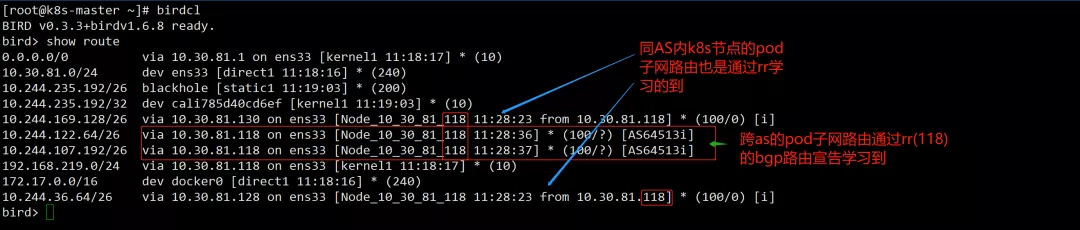
rr路由宣告
在ensp网络的R1上其应该能学习到所有k8s节点的pod子网对应的子网段路由
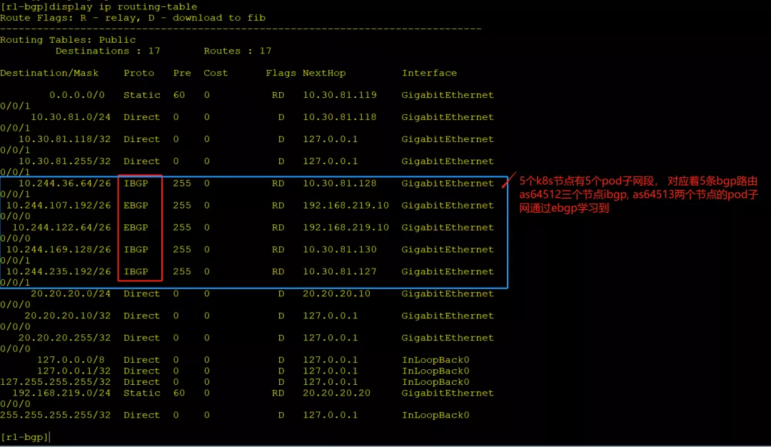
R1学习的bgp路由
接着通过跨网段节点的pod间通信抓包验证, as64512的k8s-master节点的pod master与as64513的k8s-node3的pod node3间通信抓包, 在R2上抓包
- [root@k8s-master ~]# kubectl get pod -o wide | grep -E "node3|master"
- master 1/1 Running 0 29m 10.244.235.192 k8s-master
- node3 1/1 Running 0 29m 10.244.107.192 k8s-node3
- [root@k8s-master ~]# kubectl exec -it master -- ping 10.244.107.192
- PING 10.244.107.192 (10.244.107.192): 56 data bytes
- 64 bytes from 10.244.107.192: seq=0 ttl=60 time=49.314 ms
- 64 bytes from 10.244.107.192: seq=1 ttl=60 time=28.744 ms
- 64 bytes from 10.244.107.192: seq=2 ttl=60 time=48.422 ms
- 64 bytes from 10.244.107.192: seq=3 ttl=60 time=39.144 ms
- 64 bytes from 10.244.107.192: seq=4 ttl=60 time=32.472 ms

R2抓包
如上跨节点k8s集群基于bgp实现了pod间的通信
手动维护bgp
实验过程中在ENSP部分有关R1/R2的bgp配置都是手工进行维护的, 针对每机架一个AS的部署模式, 怎么监控到一个AS内的主机的上下线, 然后自动的更新RR上client的信息。
bgp架构的思考
在本篇测试中只建立了"每机架作为一个独立as"架构的测试,该架构中最上层是采用交换机连接, 因此要求所有不同网段中的RR要建立其ebgp关系, 不一定要全互联但是要保证每个RR都可以从某一个RR学到其他剩余的RR宣告的BGP路由。"每机架作为一个独立AS"架构的另一种为最上层为路由器, 他们与所有RR都建立EBGP关系,这样在RR之间就不需要再建立BGP关系了。另外就是考虑路由条目变多后, 哪种架构更合适, 暂未涉及。
问题记录
- ensp使用云无法找到vmnet8网卡问题, 重装winPcap,重装ensp, 路由和同网段主机突然不通了可能是网卡找不到...
- ensp路由设备无效问题:见ensp界面右上角菜单查找帮助手册, 删掉页面上的所有设备重新注册, 还是失败考虑重装ensp...
- workstation在nat模式下无法连接虚机:先查主机上vmnet8网卡的ip地址,在虚拟网络编辑器中设置nat时, 设置的nat范围需要和vmnet8的ip地址在同一网段且网关设置为vmnet8的ip
- 新增k8s节点在安装必备的工具时可以先切换回桥接联网,然后再切换回nat, 然后在加入k8s集群
- ensp部分网络配置不通可以直接在路由器R1和R2的两端接口处抓包, 分析哪段不通, 哪段接到请求但是没有响应
本文为原创投稿文章,文章原文:https://larioy.gst.monster/2021/09/05/k8s-ji-chong-cni-fang-an-jie-xi/calico/ensp-mo-ni-calico-kua-wang-duan-bgp-wang-luo/
参考资料
[1]The AS Per Rack model: https://docs.projectcalico.org/reference/architecture/design/l3-interconnect-fabric